Building Elementary Blocks of Robot Motion; Powered by Jetson Nano
Recently, I’ve found myself pondering the potential of integrating embedded machine learning into my daily routine. The prospect of enhancing the enjoyment and simplifying the complexities of life, whether through a robotic assistant or improved home automation, has captured my curiosity. This blog post delves into the foundational steps of preparing the basic hardware necessary to embark on this journey.
Choosing the processor
When hobbyists consider processors for embedded applications, the Raspberry Pi is often the initial choice. However, persistent supply chain challenges in recent years have significantly hindered its availability. Consequently, I began exploring alternative candidates, and among them, the Jetson Nano emerged as the clear frontrunner. Developed by Nvidia Inc., the Jetson Nano is a compact yet potent computer. It boasts the capability to execute AI frameworks and models while maintaining impressive power efficiency. Furthermore, it is complemented by Nvidia’s JetPack SDK, enhancing its overall support and functionality
In addition, it is priced reasonably for the hardware included!
The robot we build here is similar to the Jetbot.
Building the Chassis
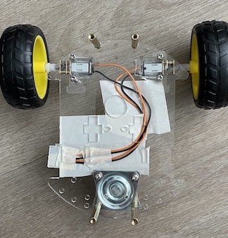
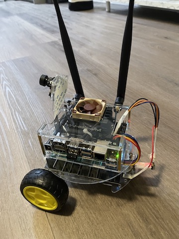
I incorporated components from this set for the load-bearing element of the project. As depicted in the accompanying images, the movement is governed by the two wheels (motors) positioned on either side and a freewheel at the rear. Instead of utilizing the motors provided in the initial set, I opted for these N20 motors, renowned for their resilience up to 6V.
The Motor Driver Circuit
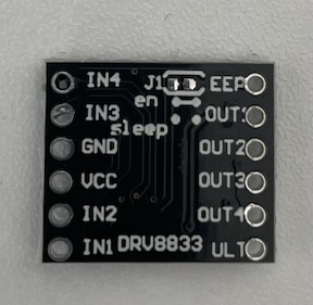
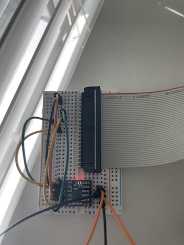
To control the movement of these motors, logical commands (or a program) are essential. Programming specific GPIO pins on the Nano is required to transmit turn signals effectively. With two motors designated as motor1 (Left) and motor2 (Right), both are operated by the DRV8833 IC, as illustrated below. IN1 and IN2 manage the turn direction signal for motor1, while IN3 and IN4 serve the same purpose for motor2. The IC’s other inputs include Vcc and GND, drawing unregulated 5V power from GPIO pin 2 for Vcc and establishing a connection from pin 14 as the GND. OUT1 and OUT2 connect to motor1, while OUT3 and OUT4 are linked to motor2. The breadboard configuration of this circuit is displayed below. The voltages from even-numbered GPIO pins (second row of the GPIO pins) have been seamlessly integrated into the breadboard via a ribbon cable.
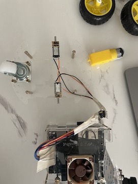
Simplifying this circuit by eliminating the breadboard and the ribbon cable, we are left with a configuration resembling the image on the left. The right image showcases the same chassis, further refined for smoother motion.
Powering the processor
To facilitate the robot’s mobility within its environment, a portable power source is indispensable. For this purpose, I’ve opted for the Waveshare UPS Power Module designed for the Jetson Nano. This UPS module requires four 18650 batteries and includes a compact OLED display. The display offers real-time information on battery voltage, IP address, RAM usage, and more, obtained through I2C pins (SDA and SCL). To activate this display, a corresponding service must be enabled on the Jetson OS. The UPS, seamlessly mounted on the chassis, is depicted below.
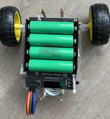
After placing the UPS, the board has been affixed on to the top layer of the chassis.
Driving the motors using GPIO Controls
Now that the physical structure of the robot is in place, the next step involves programming the logic governing its movement. The Nano boasts a 40-pin GPIO layout, closely resembling that of the Raspberry Pi. The manipulation of voltage on selected pins, configured as input signals to the motors, is the key to controlling the robot’s motion.
Specifically, GPIO pins numbered 12, 16, 18, and 22 are integral to motion control in this setup. As previously mentioned, IN1 and IN2 serve as inputs for the motor driver chip associated with motor1. GPIO pins 12 and 16 are intricately connected to IN1 and IN2, determining the direction of motor1. Similarly, pins 18 and 22 are linked to IN3 and IN4 for motor2 control. A logical high signal on IN1 (pin 12) propels motor1 forward, while a logical high on IN2 (pin 16) prompts reverse motion. Likewise, a logical high on IN4 (pin 22) directs motor2 forward, whereas IN3 (pin 18) induces backward motion.
The Code!
To propel the robot forward, both motor1 and motor2 must rotate in the forward direction. This entails setting logical highs on GPIO pins 12 and 22 (IN1 and IN4). Conversely, to drive the robot backward, the rotation of motor1 and motor2 should be reversed, necessitating the setting of pins 16 and 18 (IN2 and IN3) to logical highs.
In this context, the manipulation of signals on the board pins is facilitated through the Jetson GPIO Python library. While programming the GPIO, we adopt the BCM pin-numbering scheme from Raspberry Pi, benefiting from a convenient mapping of each board pin to a corresponding BCM number.
The following python code moves the robot 1 second forward and reverses 5 seconds!
1
2
3
4
5
6
7
8
9
10
11
12
13
14
15
16
17
18
19
20
21
22
23
24
25
26
27
28
29
30
31
32
33
34
35
36
37
38
39
40
41
42
43
44
45
46
47
48
49
50
51
52
53
54
55
56
57
58
59
60
61
62
63
64
65
66
67
68
import subprocess

import RPi.GPIO as GPIO
import time
import nanocamera as nano
from PIL import Image
import sys

# Pin Definitions
output_pin1 = 18  # BCM pin 18, BOARD pin 12
output_pin2 = 23  # BCM pin 23, BOARD pin 16

output_pin3 = 24  # BCM pin 24, BOARD pin 18
output_pin4 = 25  # BCM pin 25, BOARD pin 22


def turn_right(turn_time):

    GPIO.output(output_pin1, GPIO.HIGH)
    time.sleep(turn_time)
    GPIO.output(output_pin1, GPIO.LOW)


def turn_left(turn_time):

    GPIO.output(output_pin4, GPIO.HIGH)
    time.sleep(turn_time)
    GPIO.output(output_pin4, GPIO.LOW)


def forward(running_time):

    GPIO.output(output_pin1, GPIO.HIGH)
    GPIO.output(output_pin4, GPIO.HIGH)
    time.sleep(running_time)
    GPIO.output(output_pin1, GPIO.LOW)
    GPIO.output(output_pin4, GPIO.LOW)


def reverse(running_time):

    GPIO.output(output_pin2, GPIO.HIGH)
    GPIO.output(output_pin3, GPIO.HIGH)
    time.sleep(running_time)
    GPIO.output(output_pin2, GPIO.LOW)
    GPIO.output(output_pin3, GPIO.LOW)

def initialize():

    GPIO.setmode(GPIO.BCM)
    GPIO.setup(output_pin1, GPIO.OUT, initial=GPIO.LOW)
    GPIO.setup(output_pin2, GPIO.OUT, initial=GPIO.LOW)
    GPIO.setup(output_pin3, GPIO.OUT, initial=GPIO.LOW)
    GPIO.setup(output_pin4, GPIO.OUT, initial=GPIO.LOW)


def main(start):
    # Pin Setup:

    initialize()

    # Move forward for 1 second and stop
    forward(1)

    # Move back for 5 seconds and stop